
Two stroke Exhaust Pipe
Graham Bell
Handbook
Grigoryev
How a two-stroke expansion chamber works
An expansion chamber is not a muffler. It is a tuned pressure-wave device, and on a two-stroke engine it is worth more power than almost anything else you can bolt on. Getting its dimensions right is the difference between an engine that pulls hard and one that never comes alive.
When the exhaust port uncovers, a sharp high-pressure pulse leaves the cylinder and runs down the pipe at the speed of sound in hot exhaust gas — roughly 450 to 550 m/s, well above the speed of sound in cold air, because the gas is hot. What happens to that pulse next is the whole design problem.
The diffuser pulls, the baffle pushes
When the pulse reaches the diverging cone (the diffuser), the widening section reflects it back towards the engine as a negative, suction wave. If it arrives while the transfer ports are open, it helps drag the burnt gas out of the cylinder and pulls fresh mixture up through the transfers. This is the scavenging effect, and it is why a two-stroke with a proper pipe breathes far better than one with a straight exhaust.
That suction has a cost. In a two-stroke the transfer ports and the exhaust port are open at the same time, so the same wave that pulls out the burnt gas also pulls fresh mixture straight past the piston and out of the exhaust port. Without a second effect, you would simply be throwing fuel away.
The converging cone at the far end — the baffle — provides that second effect. It reflects the wave back as a positive pressure pulse, and if the pipe length is right, that pulse arrives at the exhaust port just before the piston closes it, and stuffs the escaped mixture back into the cylinder. This is the plugging pulse. It is effectively free supercharging, and it is where the power comes from.
Why a pipe only works in a narrow rpm band
The waves always take the same time to travel the pipe, but the crankshaft does not always take the same time to turn. Raise the rpm and the piston closes the exhaust port sooner, so the returning pulse arrives too late. Lower the rpm and it arrives too early, and the port is still wide open when the pressure gets there. The timing is only correct across a narrow band, and the centre of that band is the rpm you enter in the calculator. A pipe is a choice about where your power lives, not a general improvement.
What you need to measure before you start
Four numbers drive every method on this page. The first two decide the length of the pipe; get them wrong and no amount of care with the cone angles will save the result.
- ED — exhaust duration in crank degrees, from the moment the piston uncovers the exhaust port to the moment it covers it again. Measure it on the actual cylinder with a degree wheel. Do not take it from a spec sheet for a different barrel, and do not estimate it: a 10-degree error moves the tuned length by about 5 percent.
- n — the rpm where you want peak power, not the maximum rpm the engine will see. For a road bike this is usually well below the rev limit; for a racing engine it sits close to it.
- D1 — the diameter of the exhaust port where the pipe attaches. If the port is not round, use the diameter of a circle with the same area.
- flange — the length of the stub between the cylinder and where your pipe actually begins. It counts as part of the header, which is why the calculator subtracts it.
Tuned length: the number that matters most
Every method here starts from the same idea: the tuned length is proportional to exhaust duration and inversely proportional to rpm. Graham Bell writes it as a single expression, where L comes out in millimetres:
L = ED × 42545 / n
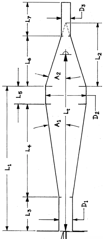
The constant carries the wave speed and the unit conversion. Take the values this page loads with — 196 degrees of exhaust duration at 11000 rpm — and it gives 758 mm. The Handbook method works the same problem in inches, as Lt = 1700 × ED / n, and arrives at 30.3 inches, or 769 mm. Two methods from different traditions, 1.5 percent apart. That agreement is a good sign that you have entered your numbers correctly; a large disagreement usually means a typo.
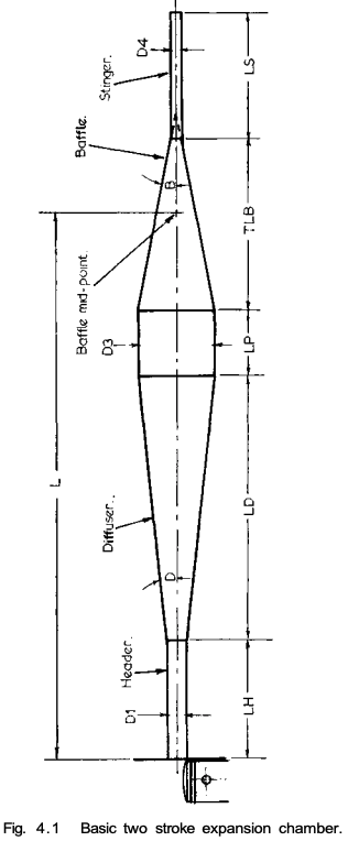
One detail trips up almost everyone building their first pipe: L is not the overall length of the exhaust. It is measured from the piston face at the exhaust port to the middle of the baffle cone. The stinger hangs off the end and is not part of it.
The three methods, and which one to trust
This calculator runs three independent design methods on the same inputs and shows all three side by side.
- Graham Bell — from Two-Stroke Performance Tuning, the standard reference in the English-speaking tuning world. You choose the cone angles and it returns the lengths and diameters. This is the method to build from.
- Handbook — a workshop-manual method that works internally in inches. It fixes the belly at 2.5 times the port diameter and the stinger at 0.6 times, so it has fewer free choices than Bell.
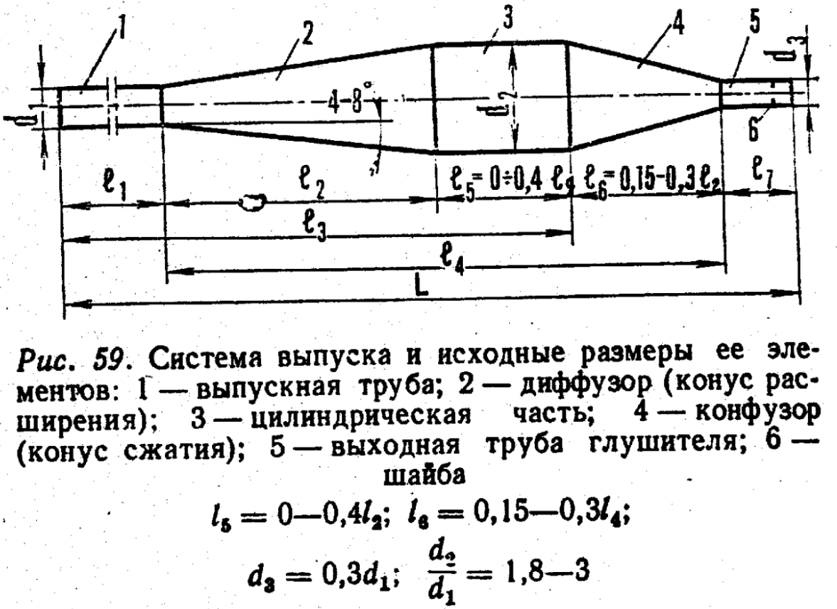
- Grigoryev — from the post-Soviet engineering school. It measures its lengths from different reference points than Bell does, so do not expect its l3 to match Bell's L. Compare the proportions, not the raw numbers.
Use Bell as the primary design and treat the other two as a cross-check. Where all three agree on a proportion — and they do agree that the belly should be about 2.5 times the port diameter — you can be confident in it.
Reading the Graham Bell output
| Symbol | What it is |
|---|---|
| L | Tuned length, from the piston face at the exhaust port to the middle of the baffle cone. |
| LH | Header length — the first, near-parallel section, with the flange already subtracted. |
| D2 | Diameter where the header ends and the diffuser begins. |
| D3 | Belly diameter — the widest part of the chamber, fixed at 2.5 times the port diameter. |
| LD | Diffuser length — the diverging cone that generates the suction wave. |
| LP | Belly length — the parallel mid-section between the two cones. |
| OLB | Baffle length continued to its theoretical apex, as if the cone closed to a point. You do not cut this length — it is a construction value. |
| TLB | True baffle length — the cone truncated where it meets the stinger. This is the one you cut. |
| D4 | Stinger diameter, as you entered it. |
| LS | Stinger length, as you entered it. |
The OLB and TLB pair is the usual source of confusion. A cone specified by an angle would close to a point; the pipe stops short of that point where the stinger takes over. OLB is the distance to the imaginary tip and exists only so the geometry can be laid out; TLB is the sheet metal you actually roll.
Choosing the cone angles
The angles are where you trade peak power against the width of the powerband. Nothing here is free.
- H, the header taper, normally sits between 1.15 and 1.5 degrees. Manufacturers have used anywhere from 0.8 to 2.3 degrees. A very long exhaust port and flange, say 75 to 100 mm, pushes you towards the steeper end.
- D, the diffuser angle, controls how sharply the suction wave is generated. A shallow cone spreads the effect over a wider rpm range but makes less peak power; a steep cone makes a stronger pulse over a narrower band. Around 7 degrees is a sane starting point for a road engine.
- B, the baffle angle, sets the strength and abruptness of the plugging pulse. It is normally 1.5 to 2 times the diffuser angle — the default pairing of 7 and 11.5 degrees sits right in that range. Going steeper buys peak power and costs powerband.
The stinger is not an afterthought
The stinger is the small outlet pipe at the end, and it sets how much pressure the chamber holds onto. Make it too small and the chamber stays pressurised, exhaust gas temperature climbs, and the engine loses power as it heats up — in the worst case it seizes. Make it too big and the waves bleed away instead of reflecting, the plugging pulse weakens, and the pipe stops working as a pipe.
A common starting point is a stinger diameter of roughly 0.58 to 0.62 times the exhaust port diameter. The values this page loads with — an 18 mm stinger on a 30 mm port — give exactly 0.60, and the Handbook method arrives at the same figure from its own formula. If you are building your first pipe, start at the larger end: a slightly loose pipe loses a little power, a tight one can cost you an engine.
When the numbers do not add up
These methods are closed-form formulas, not a solver. They will happily hand you a geometry that cannot physically exist, and the usual symptom is a negative or absurdly small length in one of the sections. What that means is that the parts you specified directly — the cone angles, the header coefficient — already consume more length than the tuned length allows, leaving nothing for the section the formula computes last.
It is not a rounding error and you cannot build around it. Steepen the cones so they take up less length, shorten the header, or accept a higher peak rpm, which shortens the whole pipe. Change one input at a time and watch which section recovers.
Treat the result as a starting point
Every method on this page assumes a fixed wave speed. In a real engine that speed follows the exhaust gas temperature, which moves with fuelling, load, ignition timing and the weather. A pipe calculated for 11000 rpm will not have its peak exactly at 11000 rpm, and no formula from any book will change that.
Expect the calculated length to be within a few percent of the best one, and plan to find the rest on the dyno or the track. If you can, build the header so it can be shortened or extended by 10 to 15 mm — that adjustment is worth more than any amount of extra precision in the arithmetic.